BGA Assembly Basics
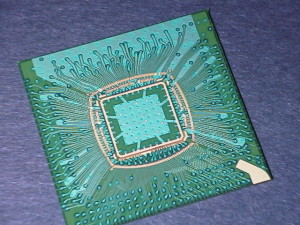
BGA (ball grid array) is a type of microelectronics packaging used in integrated circuits. The surface mount BGAs are small solder balls that are aligned in a grid, mounted permanently on the circuits in the PCB assembly process. The balls of solder are located on the bottom of the device connected directly to the board and are commonly found in CPUs and other assembly applications. They are a variation of PGA (pin grid arrays) that are an older technology replaced by BGAs. PGAs are commonly replaced in modern applications due to temperature and vibration problems. The lack of space in between the pins caused complications with the technology, which is eliminated with BGAs as they are soldered together.
Electricity is conducted between the PCB surface and the mounted device through the balls in BGAs (or pins in PGAs). The PCB has pads made of copper that are prepared on the surface in alignment with the BGA’s grid pattern. When being mounted, the PCB is heated, melting the solder balls and fusing them with the circuit board’s pads once they cool.

BGA Advantages and Disadvantages vs. PGA
BGAs have a number of advantages including:
– Limited signal distortion (due to the tighter grouping of the balls vs. pins)
– More precise alignment and mounting (prior to the BGA soldering, packaging would require many more pins)
– Less mistakes in mounting, with little to no adjacent pins being merged together (more common in PGA)
– Less prone to overheating
– Better data and application security as the mounts are less accessible
Disadvantages of BGA compared to PGA:
– Less flexing capacity than longer head PGA
– More prone to fracturing of solder joints
– Hard to inspect for soldering faults- Difficult and expensive to fix mistakes
This blog is written by San Francisco Circuits, a PCB fabrication and PCB assembly provider in Silicon Valley.
